

Flex TAPE® Commercial (2017) -- Phil Swift
Word MINE as words MY MACHINE is not the Benbot from the Benbow Inn in Garberville, California.
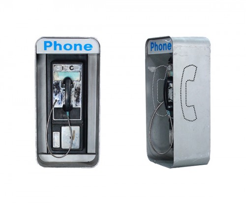
Payphone Enclosure


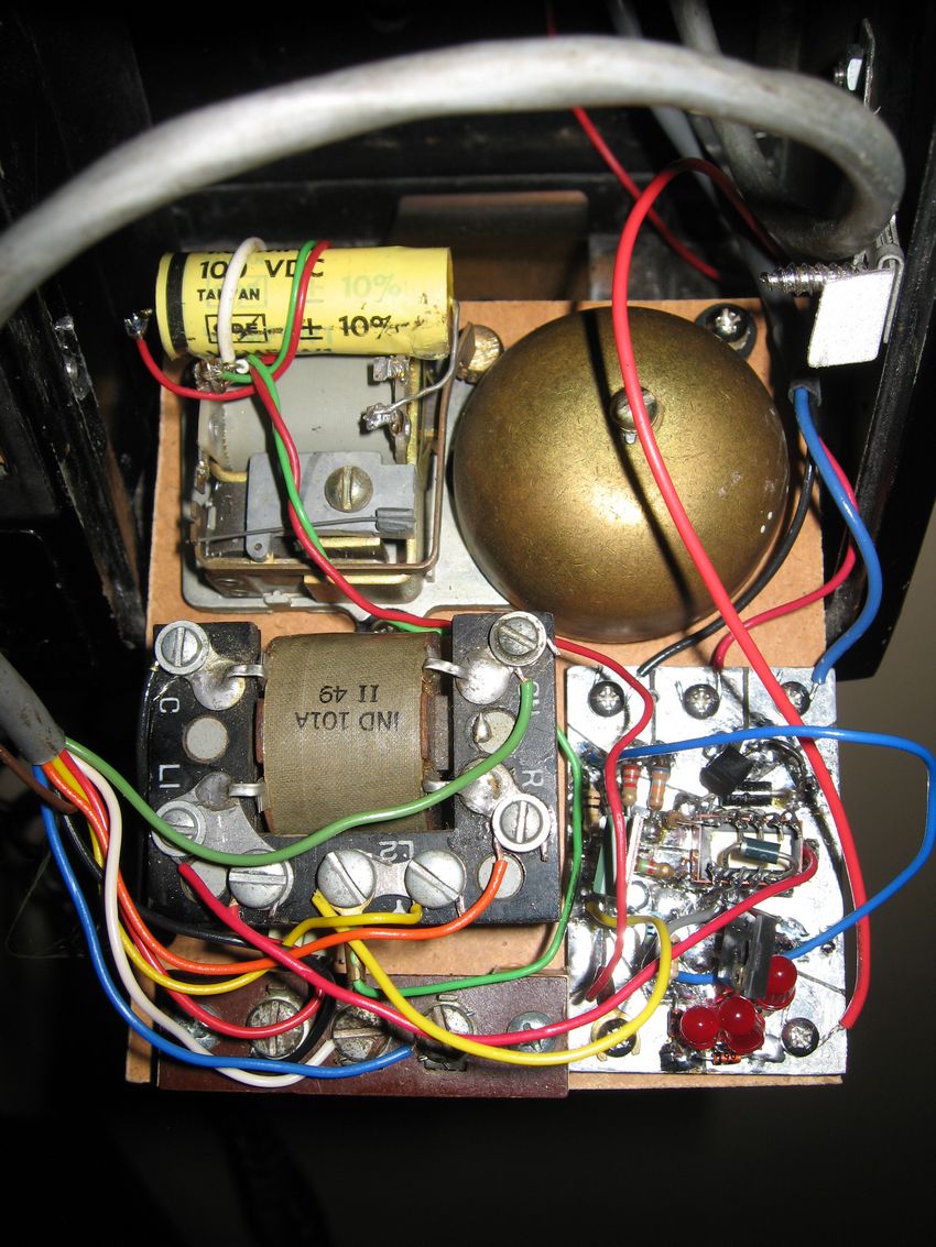
Network, ringer, and opto-switch-coin-detector mounted
on board in coin box

The first set of diagrams shown below are of my final version that uses a simple reed switch as the coin switch. The second set of diagrams and photos are of an opto-switch, coin detector that also worked, but used more parts. I have also included diagrams further down that show my original opto-switch that I built that had no moving parts. It worked, but drew too much current.
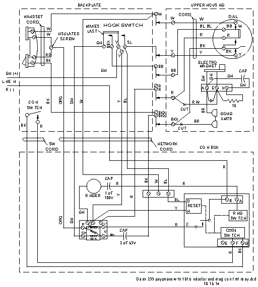 Schematic diagram of phone with magnetic-reed switch | 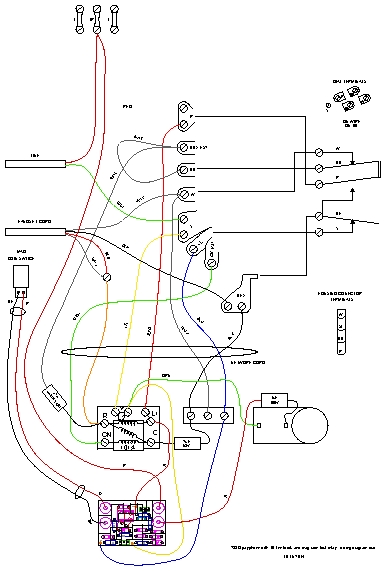 Wiring diagram of phone with magnetic-reed switch | 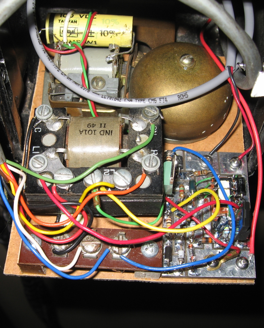 Network, ringer, and mag-switch-coin-detector mounted on board in coin box |
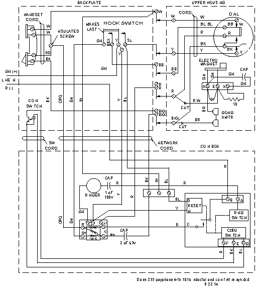 Schematic diagram of phone with opto-switch | 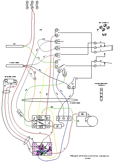 Wiring diagram of phone with opto-switch | Network, ringer, and opto-switch-coin-detector mounted on board in coin box |
Circuits
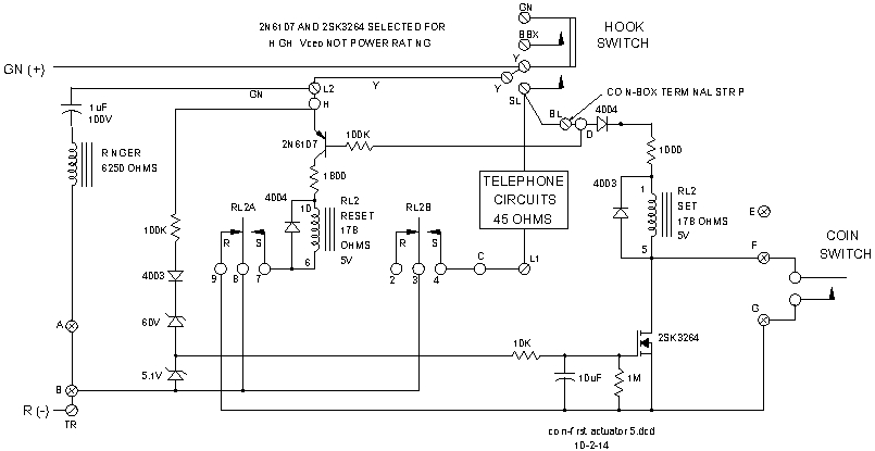 Schematic diagram of magnetic-reed-switch, coin detector | 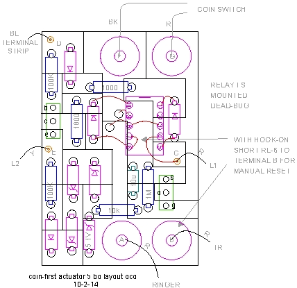 Reed-switch, coin-detector board layout |
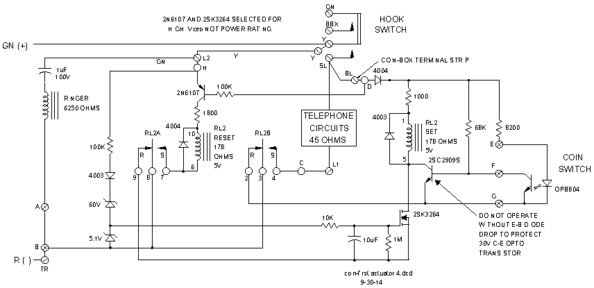 Schematic diagram of coin-detector | 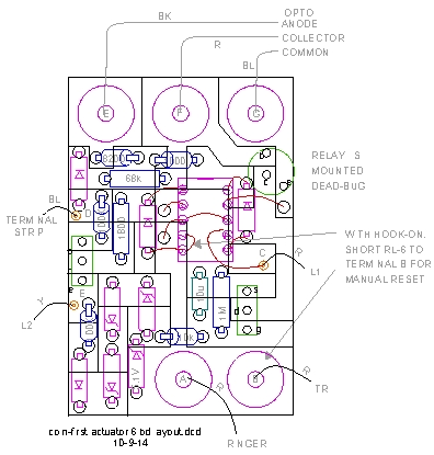 Coin detector board layout |
Sequence with incoming call:
Place coin call
Coin Switches
Magnetic-reed switch
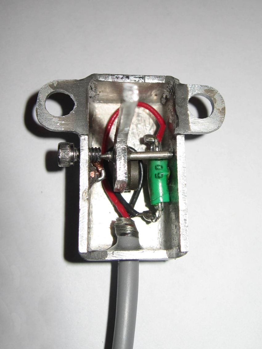
The magnetic coin switch was made from a normally open reed switch. This switch eliminated the transistor and resistor of the opto circuit and was much simpler than the opto circuit. A simple balance beam is moved by the dropping coin and a magnet on the balance beam trips the reed switch. The balance beam uses a stainless-steel, non-magnetic shaft that is sharpened on each end as an axle. The axle was sharpened by turning it in a drill press chuck and holding a grinding stone against the shaft. A dimple drilled in the aluminum switch case and another dimple drilled in a stainless-steel, non-magnetic screw serve as the bearings for the axle. Besides actuating the reed switch, the magnet provides the balance for the beam. A small piece of iron is positioned so that the magnetic attraction pulls the beam to a horizontal rest position.
Three turns of iron wire from a paper clip wrapped arround a piece of copper wire form the beam positioning ball. I moved the iron ball around the sides of the aluminum case until I found a spot where the balance beam was level. A dab of epoxy on the copper wire holds the ball in place and allows me to readjust the balls position in the future if necessary.
To mount the reed switch to the wall of the aluminum case, and be able to fine-adjust it for optimum trip point, I glued a piece of tubing to the wall as a bracket. First I found a piece of insulation that loosely fit the reed switch, and inserted the switch in the tube. After forming the leads, I put a drop of epoxy on the tube and positioned it on the wall so the center of the reed switch was nearly at the center of the magnet. A drop of finger nail polish on the tubing and the reed-switch glass holds the reed switch in its final adjustment point.
 Magnetic switch inside view | 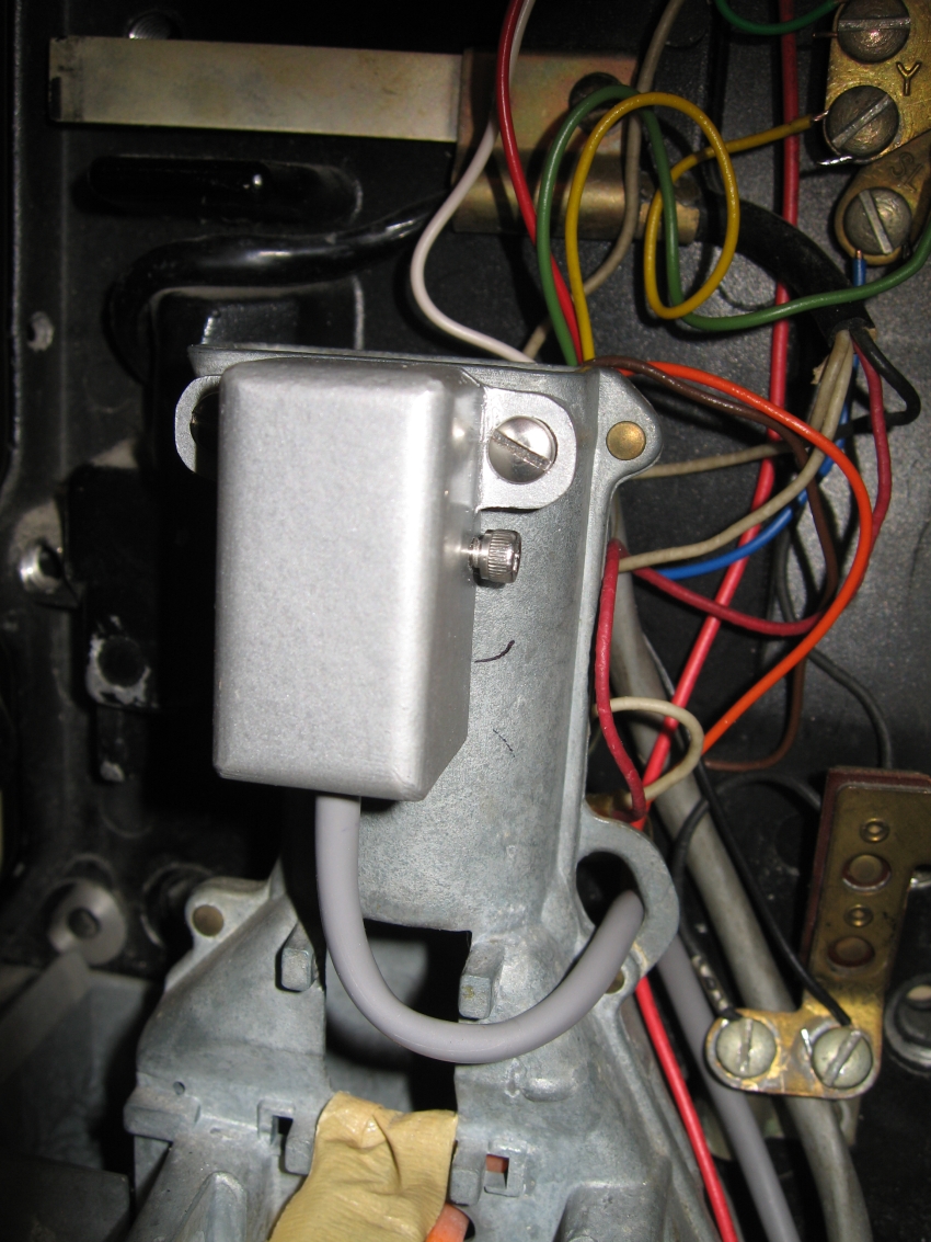 Magnetic switch mounted | 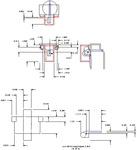 Magnetic switch dimensions |
Switches that didn't work
Long range opto switch
This is what should happen, but doesn't
The ONT 7342 is specified to detect a off-hook condition at 20 ma. There is no minimum specification, and is appears that my ONT considers greater than 8 ma to be off hook. This makes the LED drive current an off-hook condition. Although the phone is disconnected, the ONT begins timing the connection and issues a warning tone in 15 seconds then blocks dialing a number. Everything seems fine if you pick up the receiver, deposit your coin, listen for a dial tone, and dial your number within 15 seconds. If you are slow, you have to start over. I find this unacceptable and have tried several ways to get arround the problem. Reducing the LED drive current to 5 ma and making the opto-transistor into a darlington pair looked promising, but failed in the end. Several mechanical switches were tried but also failed. I tried making a mechanical switch using a very small magnet on a balance beam and a reed switch. This worked, but getting the trigger point adjusted was just too finicy for me, so I settled on my original detector circuit with a OPB804 and a balance beam to trigger it. Eventually I returned to the magnetic reed switch and made it work.
The long-range opto coin switch was made from a OPB802 opto diode-transistor interruption detector. It was cut into two pieces. What had been a quarter-inch gap was increased to about 1 inch. Don't expect a hard turn on, just a voltage dip. A big collector resistor was needed to amplify the dip, and switch the 2SC2909 relay driver.
An aluminum band around the coin shoot held the two pieces of the OPB802. Slots in the shoot are not straight across from each other, so the pieces of the opto-coupler needed to be adjusted after the band was mounted on the shoot to get the LED beam aimed at the phototransistor. The band was cut to make tabs where the opto pieces was to be mounted so the tabs could be bent for alignment.. The opto pieces were glued on the tabs cut in the band for alignment. They were kept as parallel as could be done by eyeball. The opto-coupler pieces could be taken apart to remove the LED and the phototransistor. The housing of the pieces were glued so replacement was possible without readjusting the alignment tabs.
When the band was mounted and the board connected, The one-kilohm resistor was unsoldered from the relay so it was not operating, and then the tabs were bent to get to the lowest voltage on the opto collector when the shoot was unblocked. Care was taken to not operate the opto-coupler without the 2SC2909 in place as its base-to emitter diode protected the low Vceo phototransistor from destruction.
This switch worked great, but drew 20 ma of current and the ONT thought the hook was off. All attempts to operate the LED at 5 ma failed, including using the phototransistor as a darlington pair and realigning the light beam to peak output using a a meter instead of by eyeball.
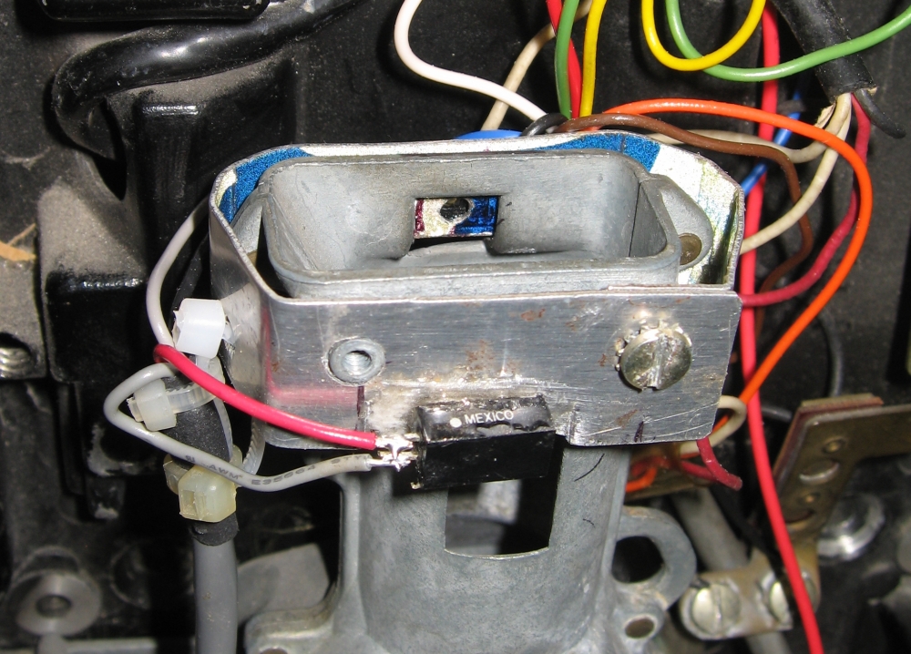 Long_range_opto coin switch |
Opto switch
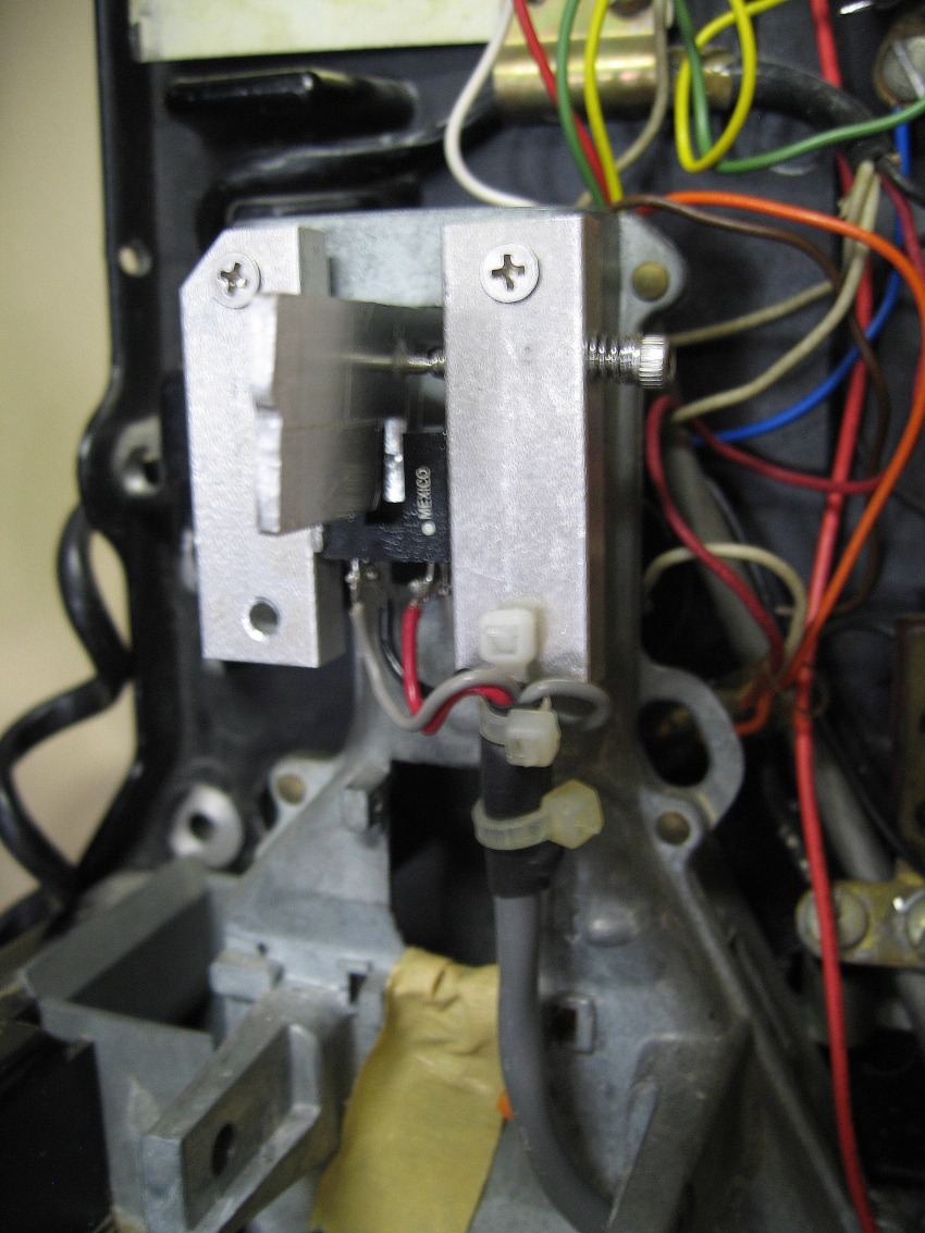 Opto balance-beam switch original version | 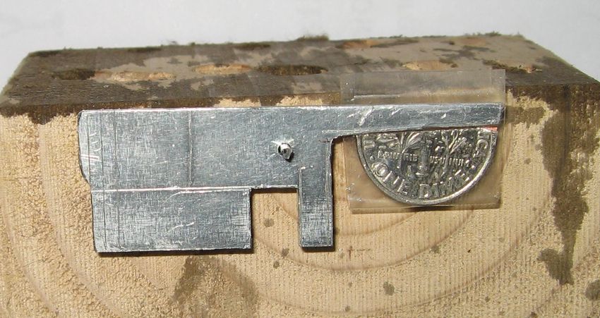 Opto balance-beam adjustment |  Opto balance-beam switch dimensions Improved version |
First magnetic switch
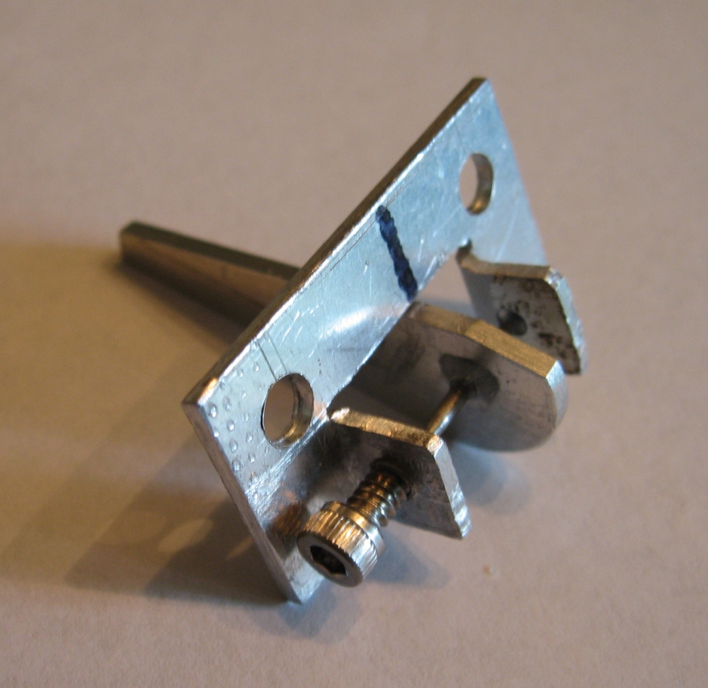
This coin switch was made from a normally open reed switch. It eliminated the transistor and resistor of the opto circuit and was much simpler than the opto circuit.
A simple balance beam was moved by the dropping coin and a magnet on the balalance beam tripped the reed switch.
The problem was the magnet was heavy, even though it seemed a small powerful one. To get a dime to move the balance beam, the magnet had to be very close to the balance beam shaft. The reed switch position adjustment to get a reliable off-on transition was very difficult. The difference in angle between on and off seemed large enough that a dime might slip though the hopper without triggering the coin detector.
I laid out a new circuit board for the magnetic switch, but never built it until I made mag-switch version two. Although this switch was a failure, It gave me a starting point and an experimental test bed for making the current magnetic-reed switch.
 Magnetic coin switch |


No comments:
Post a Comment